It arrived and I’m stoked. Loving the battery life and the simplicity.
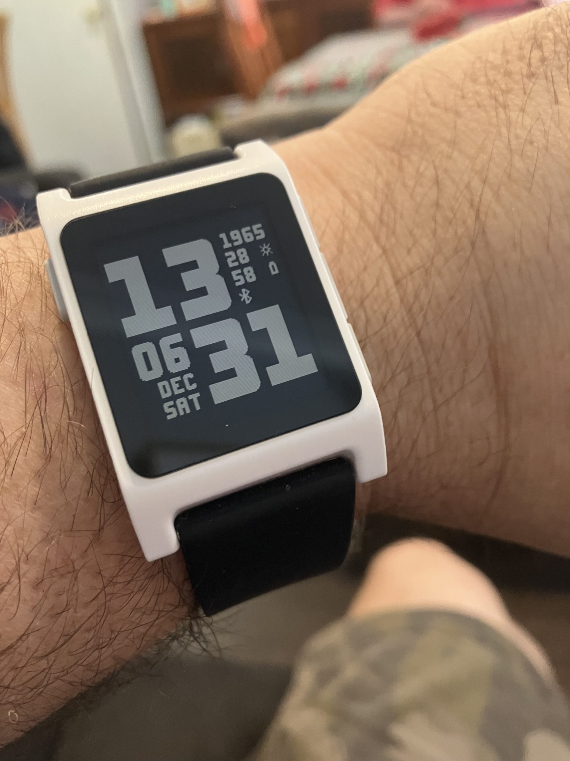
Pebble 2 Duo (white) with generic black strap. Watchface is BlockFace by TomHol.
It arrived and I’m stoked. Loving the battery life and the simplicity.
Pebble 2 Duo (white) with generic black strap. Watchface is BlockFace by TomHol.
This is awesome. I have a White Pebble 2 Duo on the way.
I had great difficulty getting my Arduino Opta set up and working using the Arduino PLC IDE – whatever I tried I got the “Cannot download Sketch file (error code: 1)” error.
I finally had success using the plain Arduino IDE to do the initialization and then switching to the Arduino PLC IDE. The final step was changing the Modbus address to 247.
It probably shouldn’t be that tricky….
So I’ve finally bought myself one of the new M1 Macs – my first new computer in nearly 10 years. I went with the 16GB unified memory model with 8-core CPU, 8-core GPU and 1TB SSD. Not very cheap but I’m hopeful I will get 5+ years of service out of it.
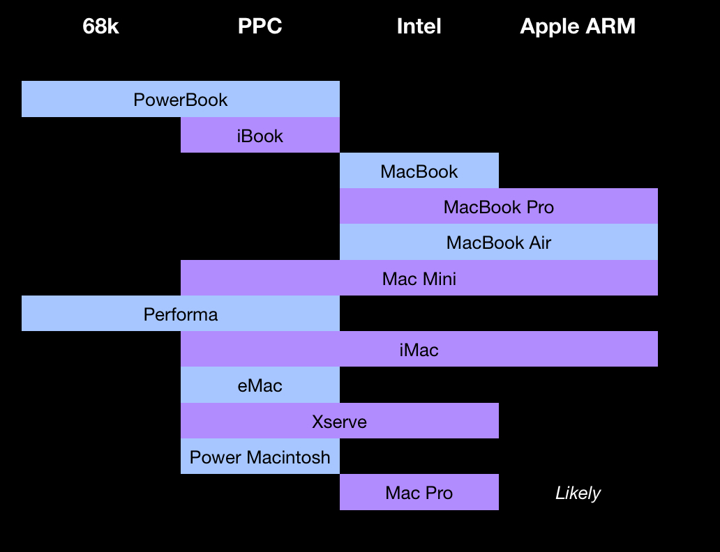
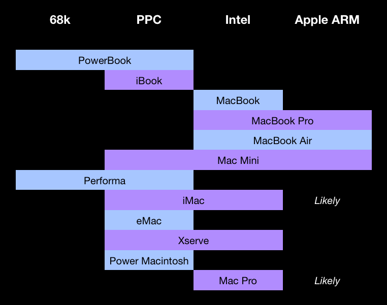
At the moment, the Mac Mini is unique in that it spans three processor architectures (although this is very likely to be matched by the iMac).
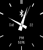
After some trial and error (and leaning heavily on the tutorials and sample code available online) I have built a Pebble watchface (named gWatch for obvious and boring reasons). It’s fairly basic – see the screenshot below.
After a fair amount of trial and error I now have the Pebble SDK working on my Mac (macOS 10.15.4 Catalina). I was working from the guide here. I can now create, build and deploy programs and watch faces to my Pebble watch.
Firstly I had problems with the virtualenv command:
cd ~/pebble-dev/pebble-sdk-4.3-mac
virtualenv --no-site-packages .env
source .env/bin/activate
CFLAGS="" pip install -r requirements.txt
deactivate
It turns out the –no-site-packages flag is not required and should be omitted (see here for details).
I then had issues with no SDK being installed (and the scripts trying in vain to locate the SDK on the Internet). After trying:
pebble new-project testingI was greeted with:
No SDK installed; installing the latest one...Consulting Google yielded:
The key part of the reddit post is path to the SDK. I used the following to successfully install the SDK:
pebble sdk install https://github.com/aveao/PebbleArchive/raw/master/SDKCores/sdk-core-4.3.tar.bz2The last fix was disabling the analytics tracking by creating a NO_TRACKING file in the SDK directory.
For a while I’ve been tinkering around with a simple project – an Arduino-based temperature (and humidity) monitor that outputs a webpage on my home LAN. The Arduino I used was the Freetronics EtherTen, a quality product.
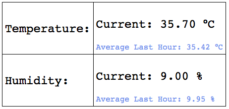
Check out the code at https://github.com/gjhmac/TempMonHTTP.
If you require an SD card interface for your Arduino project I highly recommend purchasing an Arduino with one built-in. It took three attempts to get an SD card interface added to my basic Arduino Mega:
I would have been better off spending the extra coin on a Mega with the SD card interface built-in and reclaiming most of my weekend…