// ————————————————————————————————————————————————
// Project: DataLogger
// Version: 0.4
// Date: 26 August 2018
// Author: Greg Howell <gjhmac@gmail.com>
// ————————————————————————————————————————————————
// Version Date Comments
// 0.4 26 August 2018 Modified code to only log to the SD card if the new value is different to the old value
// 0.3 30 June 2018 Added debugging and diagnostics on serial port, sped up ADC for analogue read (128kHz -> 1MHz), fixed “A REF”
// 0.2 26 April 2018 Addition of switch to enable/disable logging to SD card and LED to indicate logging status
// 0.1 17 February 2018 Initial Development
//
// ————————————————————————————————————————————————
// Description:
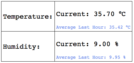
// – Logs analog0 value to a text file on the SD card along with date/time stamp in CSV format
// – Maintains date/time via DS1302 Real Time Clock
// – Builds with Arduino 1.8.5
// ————————————————————————————————————————————————
// #includes
#include <SPI.h> // Serial Peripheral Interface
#include <SD.h> // SD Cards
#include <DS1302.h> // DS1302 RTC
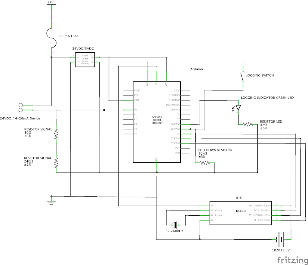
const int chipSelect = 4;
const int buttonPin = 5; // Pin 5 is the button to enable/disable logging (digital input)
const int ledPin = 6; // Pin 6 is the LED indicate logging status (digital output)
const byte PS_128 = (1 << ADPS2) | (1 << ADPS1) | (1 << ADPS0);
const byte PS_16 = (1 << ADPS2);
int buttonState = 0; // initialise button state to off
int oldsensor; // variable to store the previous sensor value (used in loop())
// Init the DS1302
// Pin 2 = RST
// Pin 3 = DAT
// Pin 4 = CLK
DS1302 rtc(2, 3, 4);
// ————————————————————————————————————————————————
// setup()
// ————————————————————————————————————————————————
void setup() {
ADCSRA &= ~PS_128; // remove prescale of 128
ADCSRA |= PS_16; // add prescale of 16 (1MHz)
analogReference(EXTERNAL); // Analogue reference set to “A REF” pin
pinMode(buttonPin, INPUT); // Initialize the pushbutton pin as an input
pinMode(ledPin, OUTPUT); // Initialize the LED pin as an output
rtc.halt(false); // Set the clock to run-mode
rtc.writeProtect(false); // and disable the write protection
Serial.begin(9600);
// Use following lines once to set clock if battery fails (modify to suit)
//rtc.setDOW(SUNDAY); // Set Day-of-Week to FRIDAY
//rtc.setTime(21, 50, 0); // Set the time to 12:00:00 (24hr format)
//rtc.setDate(26, 8, 2018); // Set the date to August 6th, 2010
while (!Serial) {
; // wait for serial port to connect. Needed for native USB port only
}
// Print current system date from RTC at start up
Serial.print(“System date: “);
Serial.println(String(rtc.getDateStr()) + “,” + String(rtc.getTimeStr()));
Serial.print(“Initializing SD card…”);
// see if the card is present and can be initialized:
if (!SD.begin(chipSelect)) {
Serial.println(“Card failed, or not present”);
// don’t do anything more:
while (1);
}
Serial.println(“card initialized.”);
}
// ————————————————————————————————————————————————
// loop()
// ————————————————————————————————————————————————
void loop() {
String dataString = “”; // make a string for assembling the data to log
int sensor = analogRead(A0); // read analogue
dataString += String(sensor); // construct string with analogue signal
buttonState = digitalRead(buttonPin); // read button state
// Logging enabled
if (buttonState == HIGH) {
File dataFile = SD.open(“datalog.txt”, FILE_WRITE);
// if the file is available, write to it
if (dataFile) {
// if the new data is different to the old data write it to file
if (sensor != oldsensor) {
// Write data to serial output
Serial.println(String(rtc.getDateStr()) + “,” + String(rtc.getTimeStr()) + “,” + dataString);
Serial.println(String(sensor) + “,” + String(oldsensor));
// Write data to SD card
dataFile.println(String(rtc.getDateStr()) + “,” + String(rtc.getTimeStr()) + “,” + dataString);
dataFile.close();
}
else {
dataFile.close();
}
// set logging LED to high
digitalWrite(ledPin, HIGH);
}
// if the file isn’t open, print an error
else {
digitalWrite(ledPin, LOW);
Serial.println(“error opening datalog.txt”);
}
}
// Logging disabled
else {
// set logging LED to low
digitalWrite(ledPin, LOW);
}
// set the old sensor value to the current sensor value (read at top of loop())
oldsensor = sensor;
// Wait before repeating 🙂
delay (500);
}